Fluke 8200A Multimeter Repair
I have a fascination with esoteric multimeters, which is particularly attracted to late 70’s and early 80’s scopes that used Nixie tube and Panaplex tube displays.
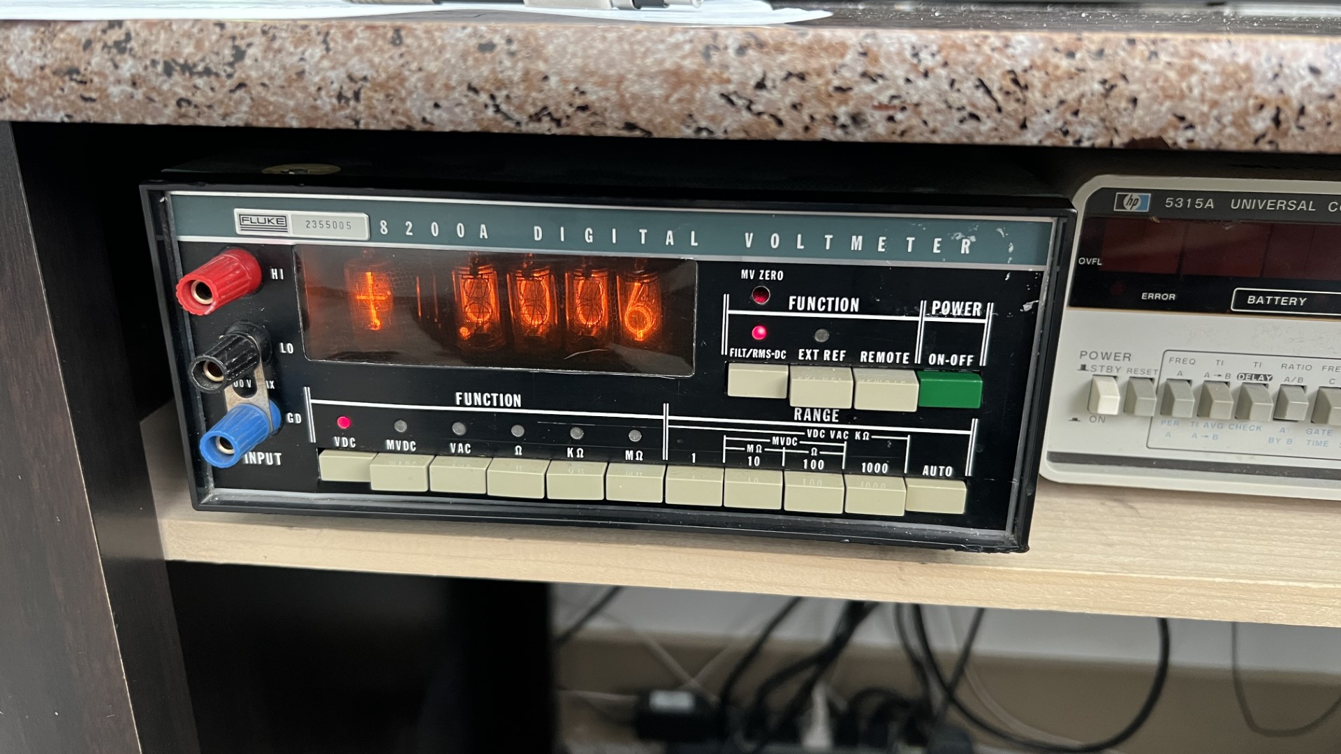
In my small but respectable collection, I have a Fluke 8200A that works well.
This is a 4 1/2 digit meter that uses Nixies for its display.
The Problem
Recently, I needed to leave the scope powered on for about one hour, and when I returned the Nixie display was completely dim.
Cycling the meter revealed that the display would turn on briefly, and continue getting dimmer and dimmer until it appeared off.
If you don’t know, Nixie tubes (and other tube based displays) require about 200VDC to power the tubes.
This means that they require a digital logic board to do the digital conversion which is tolerant of the high voltages, as well as a 200VDC power supply.
Investigation
Immediately suspect is the power supply. The power supply board on this meter is pretty simple. It takes 3 AC lines from a transformer as input and runs a simple linear regulator for each output (5VDC, 15 and -15VDC, and 200VDC). Fluke nicely has a set of test points for each one, and a troubleshooting procedure for each rail.
Of course, the 200VDC rail is the important one here, but first I inspected the board overall.
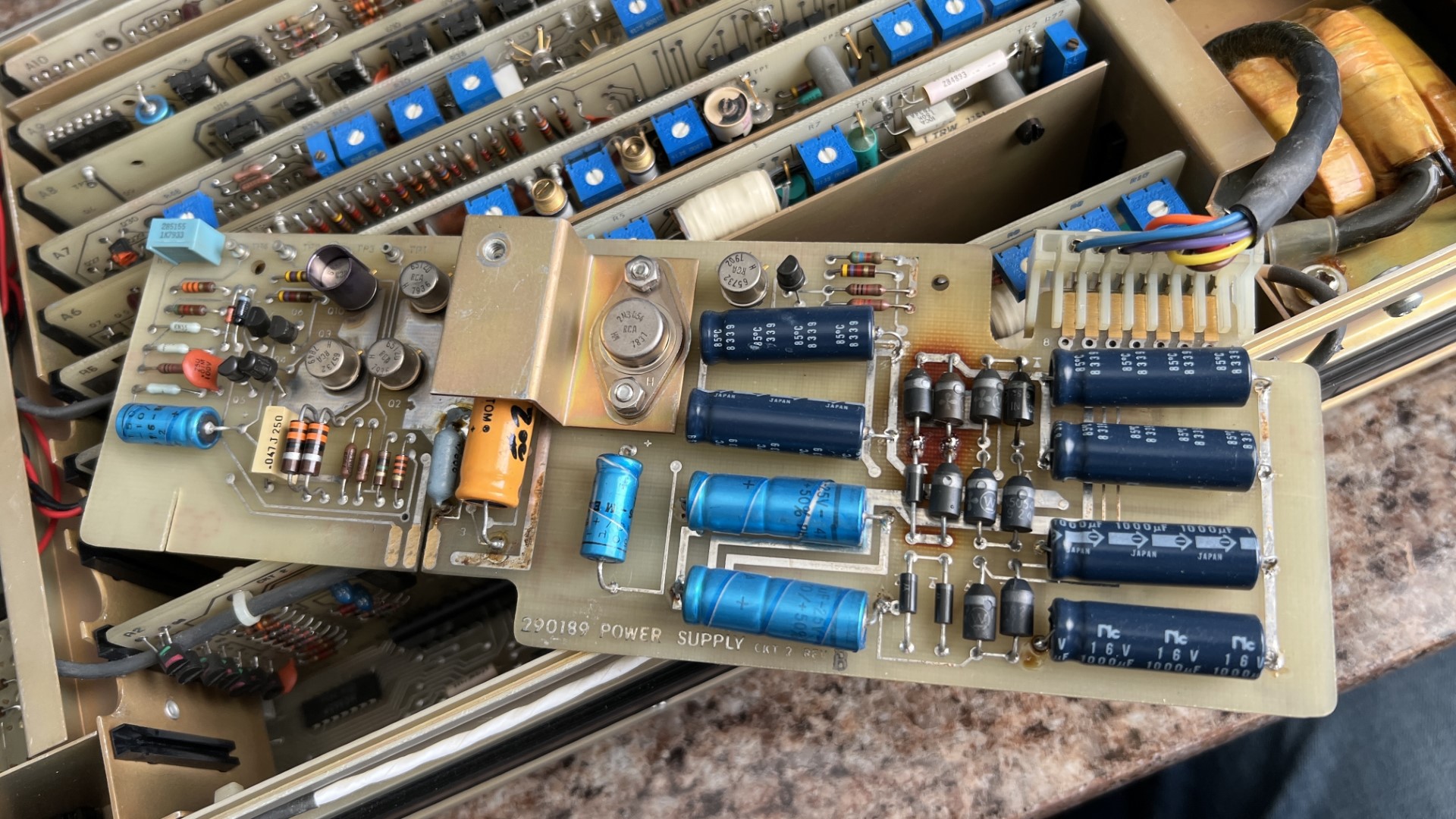
I was immediately drawn to the discoloration at the diode rectifier arrays.
Closer inspection revealed that those are the diodes for the 15V/-15V rails. I also verified that they weren’t getting hot with the board at idle, and left them as is. The board has signs of previous repair (the electrolytic filter caps near the input) and the orange cap in the middle of the board. Perhaps that was an old problem, and not immediately relevant to this new issue.
I then followed the manual’s inspection procedure for the 200V rail, and observed it outputting 140V, which is consistent with the dim display.
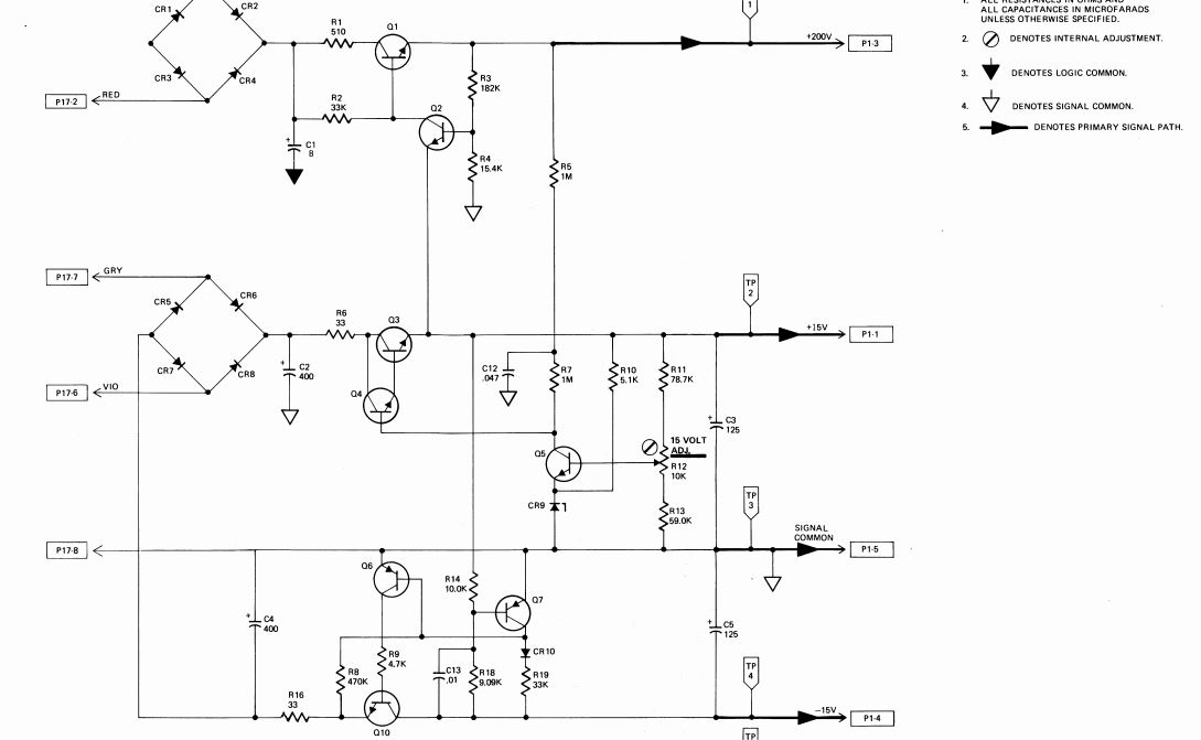
According to the schematic, there isn’t much between the rectifiers and the output that can affect the 200V rail. First, is the 8uF filter cap on the output. This is the orange cap in the middle of the board. This was easily confirmed to be acceptable by using an oscilloscope to validate the ripple on the cap under power, as well as the voltage. Both were okay, and just to make sure I removed the cap to check its ESR. At about 5 ohms for this HV cap, that also was okay.
Next, was to check the active components of the voltage regulator.
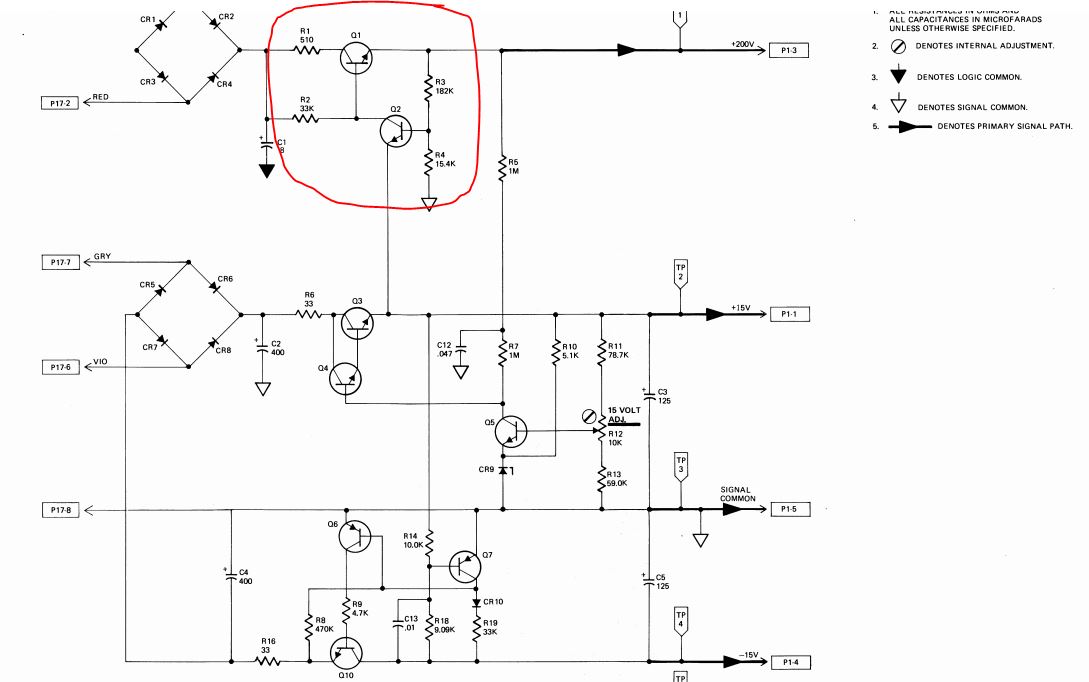
This is a very clever regulator. I would have expected to see a Zener diode in here, or in a more modern design an LM78xx family 3 terminal regulator (although I don’t know if those are available such high voltages).
It appears that Q1 conducts when C1 gets enough charge, and Q1 sets a voltage to the base of Q2 based on the resistor divider network R3 and R4. Q1 output is balanced because when the R3/R4 network provide enough current to Q2, Q2 provides a low impedance path as an alternative to the base of Q1, and therefore proportionally reduces the gain provided by the transistor.
If there is one thing to take away from this simple repair, I think it would be the design of this regulator. Searching on the web didn’t reveal much information on this type of design.
Critical Temperature
After the board was running for a bit, I discovered that R2 had reached a temperature of 100C and Q2 was close to 50C. Although R2 needs to dissipate quite a bit of energy, it was unlikely to be this amount.
This indicated that Q2 was acting abnormally.
Q2 was removed, and given the diode test with a multimeter. It passed.
Since Q2 passed, Q1 was removed on the suspicion that it was acting improperly as well. However, Q1 also passed the diode test.
Without a means to further test the transistors (I have a Tektronix 577 curve tracer, but it needs a repair, so it was unavailable today), I decided to trade Q1 for Q2 and vice-versa. (Note, Q1 and Q2 are the same transistor type, RCA 65120). Unfortunately, RCA 65120 appears to be a Fluke specific transistor, and I didn’t immediately find a replacement.
Resolution
To my rejoice, exchanging the transistors worked!
Given the lack of available new replacements for either transistor, it was determined that this was enough for this issue.
Left unresolved is a potential over-current condition on the 15V rail (remember the burn marks!). Unless something else becomes a symptom, it will stay that way. Inspection showed that the PCB lands for those 4 diodes were damaged in the event, so I retain an advantage by not touching them.
Additionally, I might continue searching for a transistor replacement. The hypothesis on the failure is that Q2 naturally exists with a high power dissipation. Basically, R2 will drop quite a bit of voltage, and even with a low resistance, Q2 will drop the remainder to 15V, even with low resistance will consume a bit of power.
Over time, this must have negatively affected the transistor in a way that Q1 was not affected. Switching the transistors should be enough for a temporary solution.
Further Investigation
After repairing my Tektronix 577 Curve Tracer, I can compare the transistors to see why swapping them worked, and what is wrong with the one.
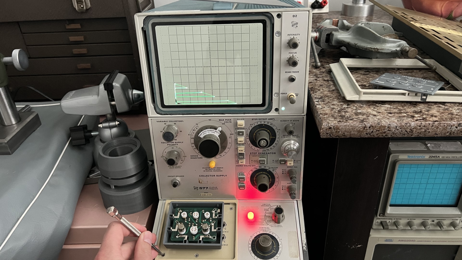
Here is the good transistor:
and the bad:
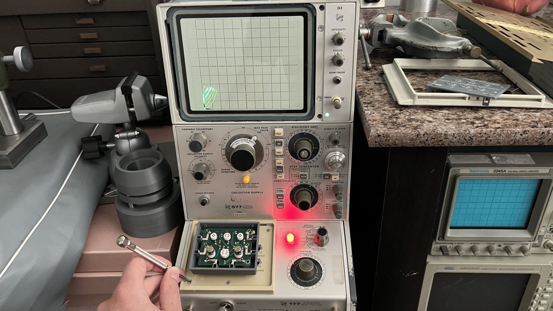
Yikes! Although not completely destroyed, the bad transistor is definitely becoming a short circuit. The theory is that having the bad one on the 200V power line still can provide power to the Nixies, and the good one as the regulator keeps the voltage in line.
In the future, ordering a few high voltage NPNs is a good idea, but I’ll keep it in this configuration for now.
Using the curve tracer, here are the specifications of the good RCA 65120:
VBRCEO: 360V
VBREBO: 9V
VBRCBO: 450V
hfe: 20-30
For bonus fun, I drew the schematic and PCB in kicad.
You can reference the files here.