Upgrade to a better headstock
The Project
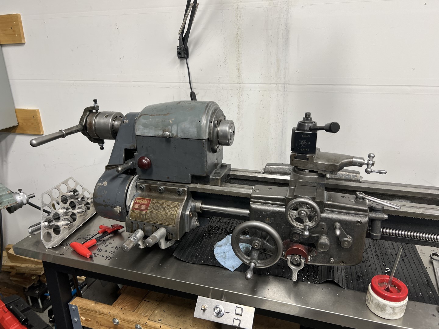
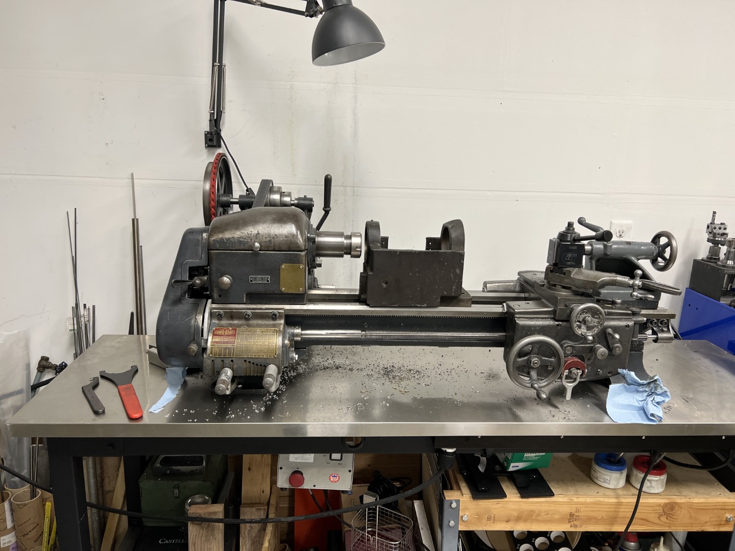
I have a logan 10” lathe that was built in 1946 and sold under the Montgomery-Ward brand. Well, it’s most correct to say that I had a logan 10” lathe.
If you didn’t know, logan used the same beds on their 10, 11, and 12” swing lathes. This makes the 10” lathe compare very favorably to comparable South-bend models of the same size. Since they aren’t as well known as South-Bend, logan models can be found more affordable too. Logan also provisioned the larger swing lathes with a significant improvement in spindle size and geometry. The 11” lathe headstock used a 1-3/8” spindle bore, suitable for 5C collets (compare to the 25/32” through bore of the 10” lathe).
I recently completed upgrading the carriage/apron on the old lathe to use the newer automatic apron. Next, was upgrading the headstock.
The New Headstock
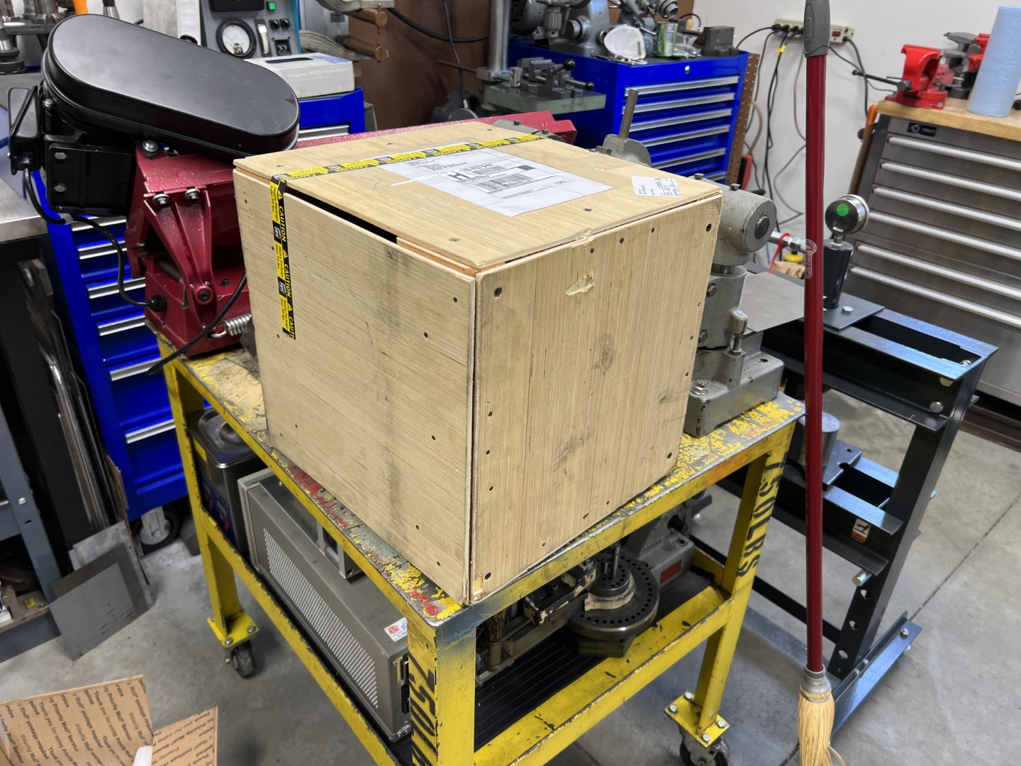
The new headstock was purchased on eBay. I could still check most of the condition visually, for example, that there were no missing gear teeth. Bearings where a concern, but I knew in advance that Logan used standard deep groove ball bearings for spindle bearings.
The unit was nicely shipped in a wooden crate and received without drama.
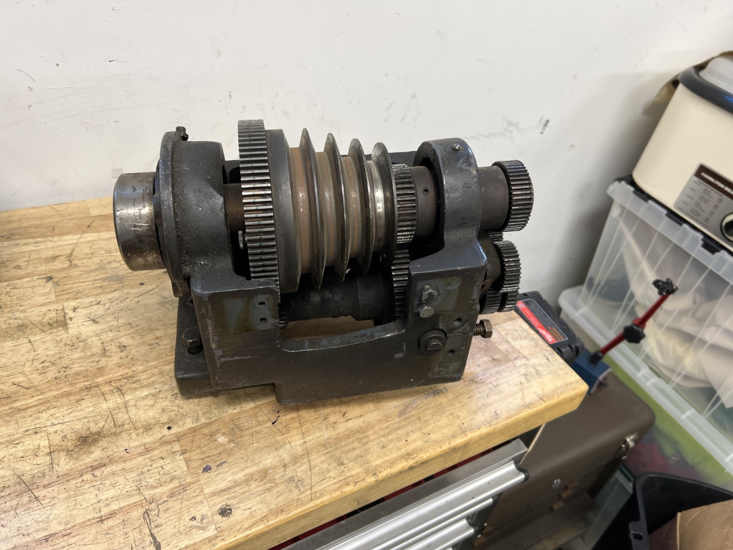
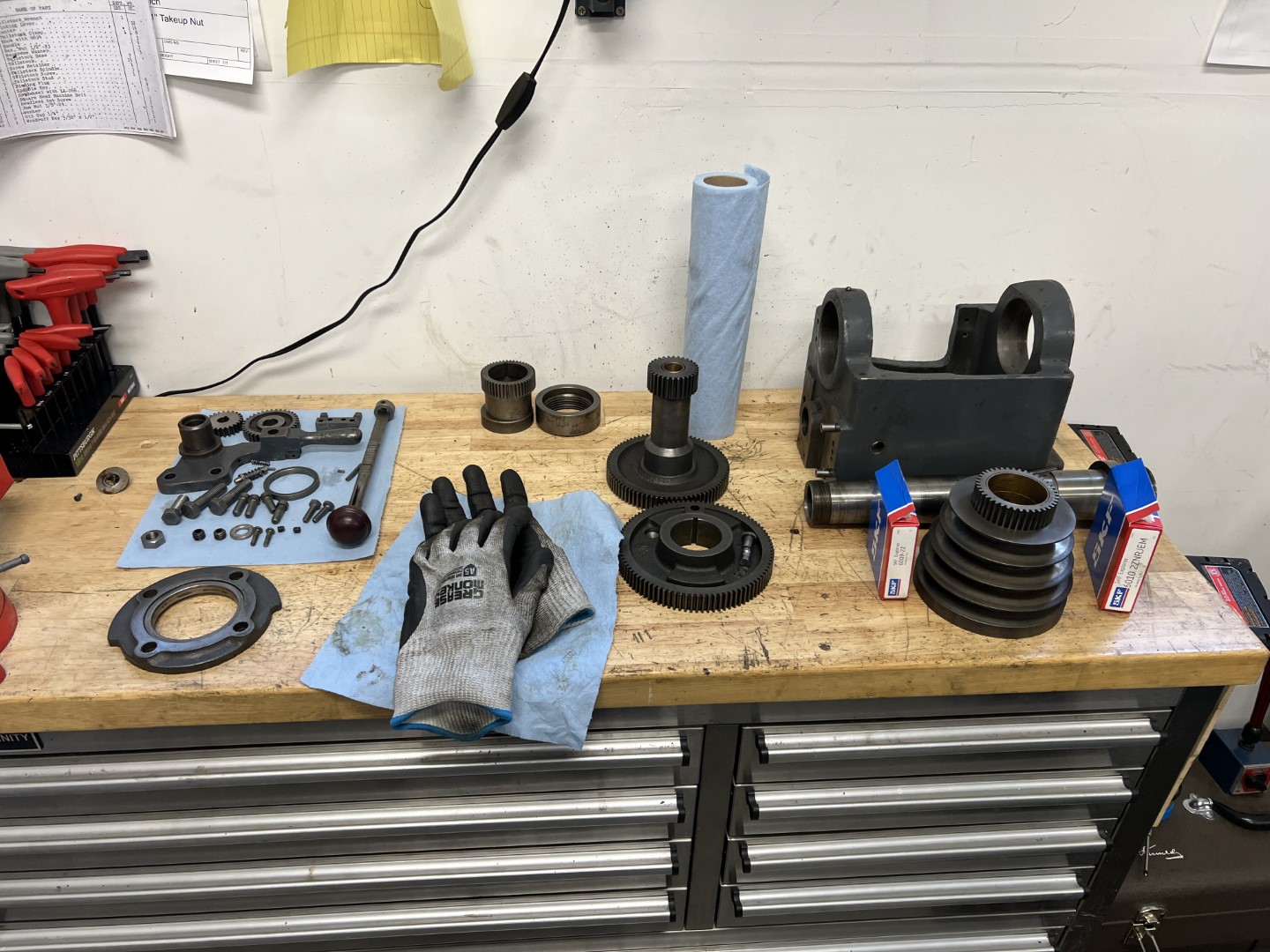
Upon receiving the unit, I disassembled and inspected it. I was happy to see a hardened and ground spindle, in very good condition. The current bearings were gummy though, but everything else was in good working order.
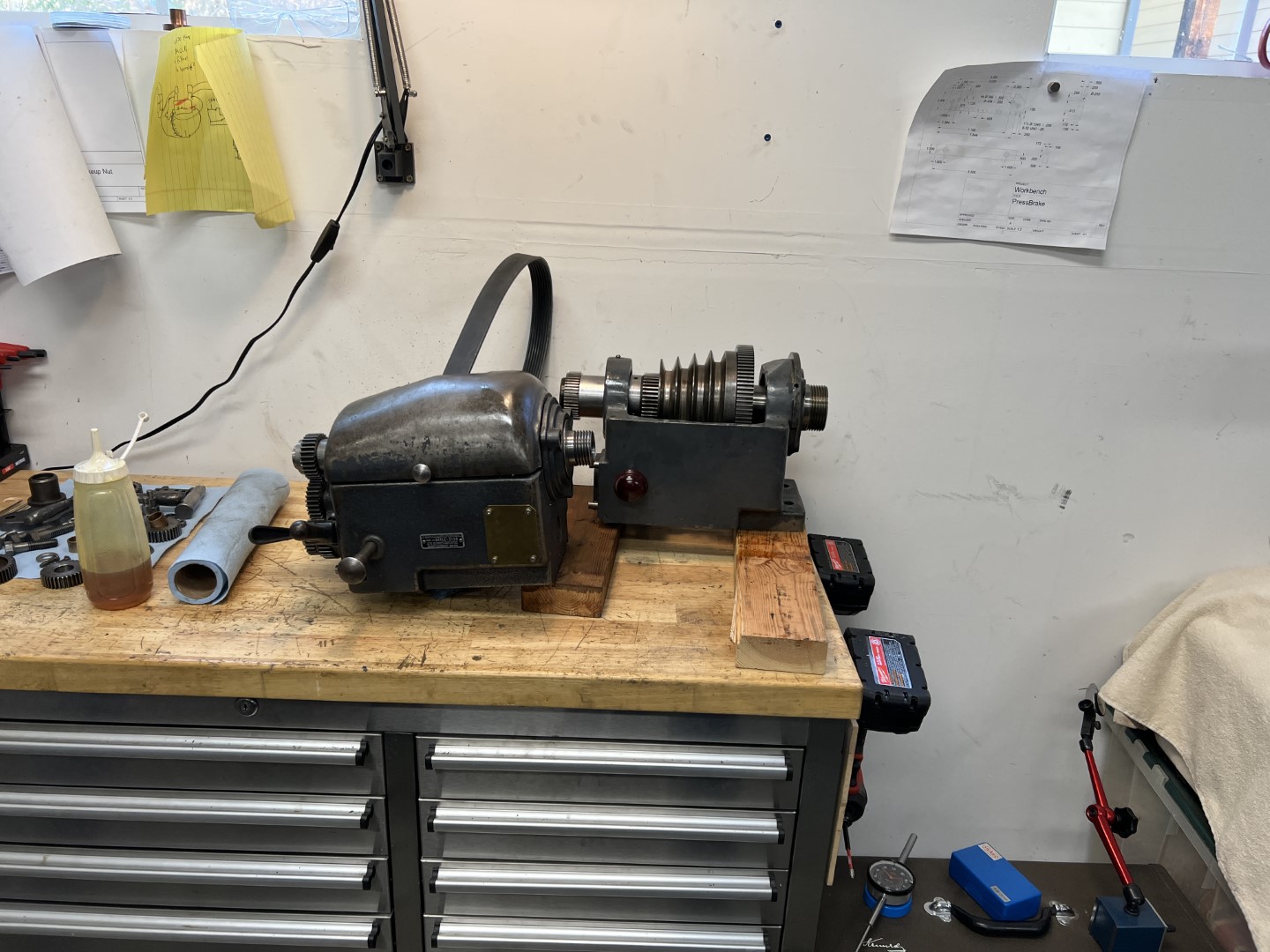
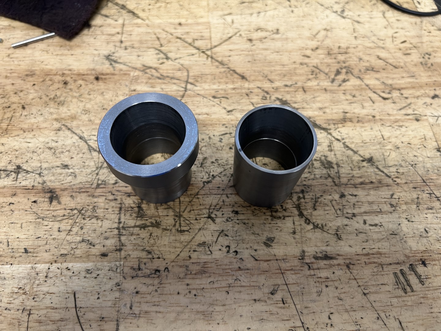
Here shown in comparison with the 10” spindle housing.
A new tailstock is required too! The 11” tailstock is more sturdy than the already sturdy 10”, with longer ram stroke too.
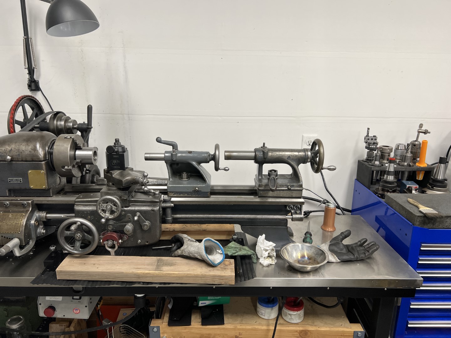
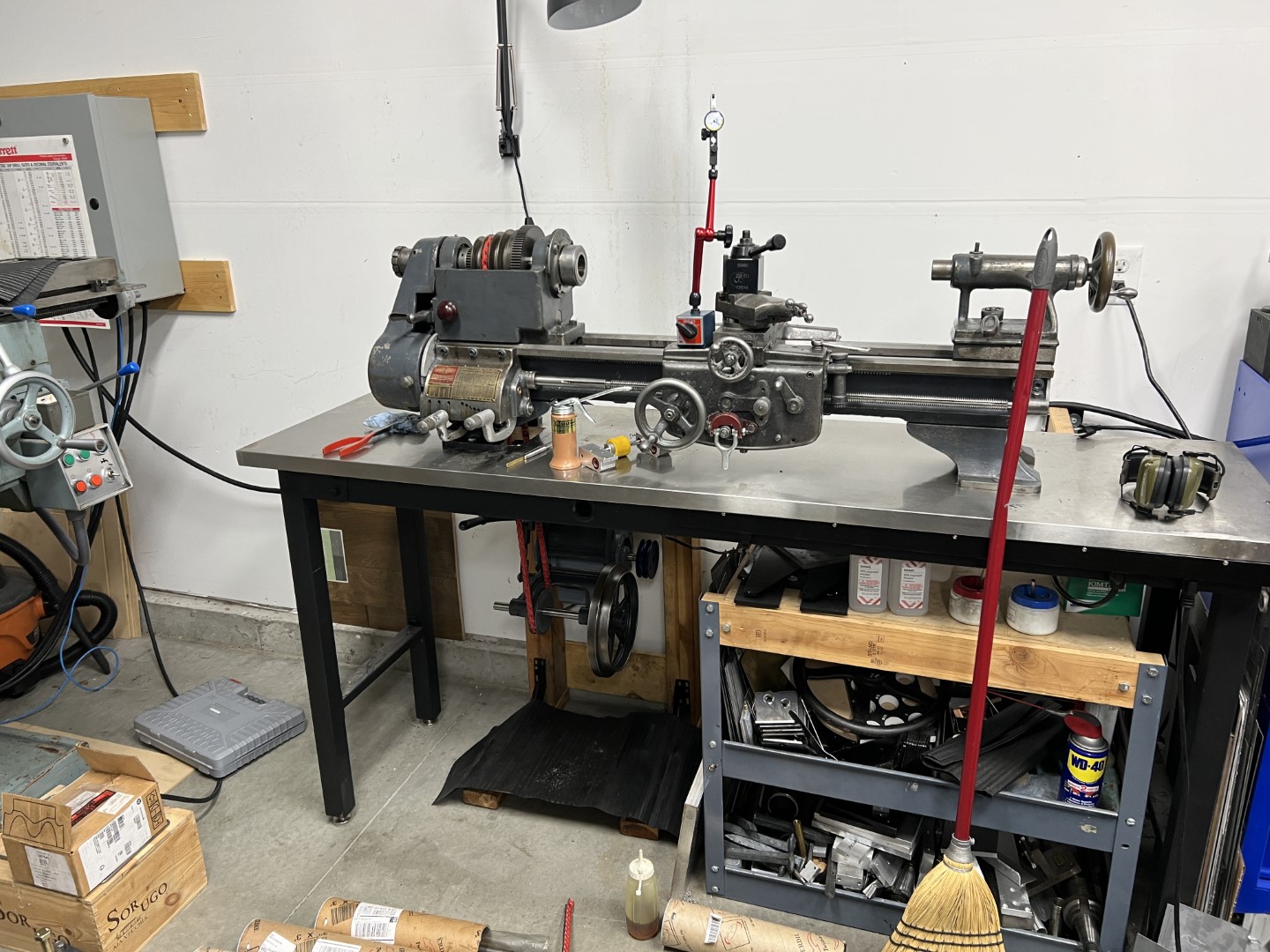
After cleanup, the new headstock and tailstock can be “installed”.
New Headstock Bearings
One primary concern with any used lathe headstock is the condition of its spindle bearings.
The topic of spindle bearings in general is beyond the scope of this blog, and converted well elsewhere. I did however, need to purchase new ones.
If you are familiar with Logan lathes, you know that new parts are still available for them!
In the 10” logan configuration, the front headstock bearing is a special order, internally preloaded double row deep groove ball bearing with locating ring. Logan specially designed this bearing for use in their lathes so that the spindle would not require preloading and potentially matched pairs of more expensive bearings. The downside is, these are not available direct from any bearing vendor. They can still be purchased from Logan, although they are very expensive.
Curiously, the 11” Logan lathe was designed to use standard single-row deep groove ball bearings for the spindle. This is in contrast to other manufacturers of a similar time period, who used taper roller bearings or poured babbit.
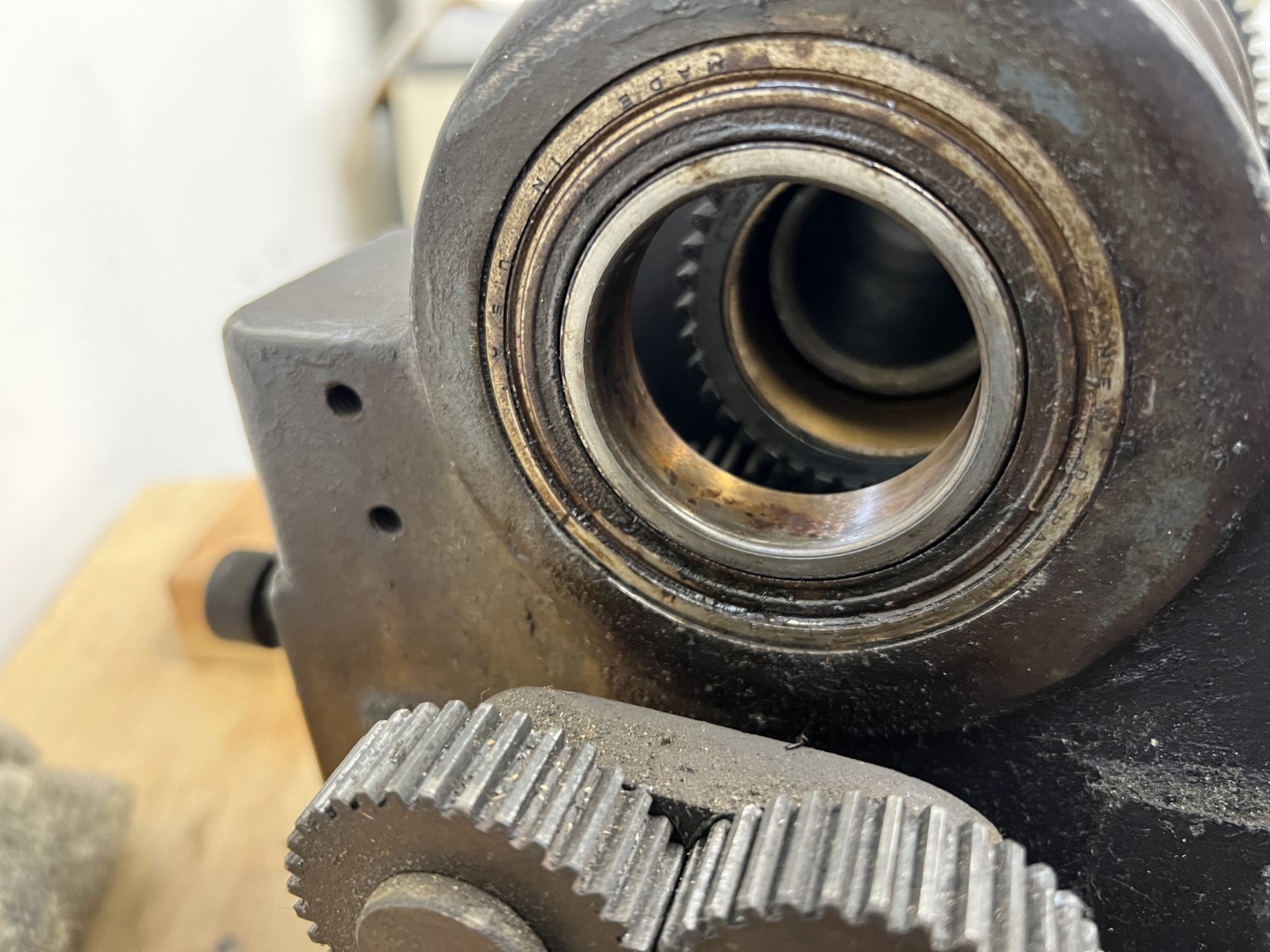
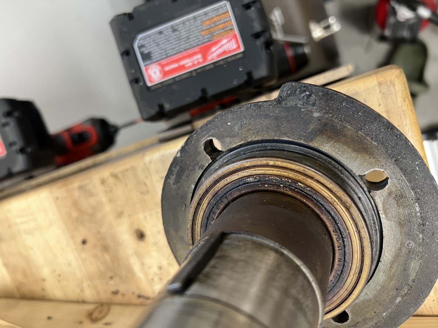
The front headstock bearing is a 50mmx80mm bearing. Logan sells replacements for $169, which is expensive but not astronomical. I decided to buy one directly from Logan, because it is not clear what specifications the bearings are made to.
To my surprise, an SKF Explorer arrived! Armed with this knowledge, I bought my own rear bearing for a significant discount. Now, these are not exceptional bearings, but the headstock arrangement doesn’t permit a higher capacity bearing without modification.
The bearing numbers are:
- 6010 2ZNRJEM
- 6009 2Z
How much axial force do these bearings load? A simple model of this is to press the carriage against a fixed surface to measure the force. Here shown with a dynamometer.
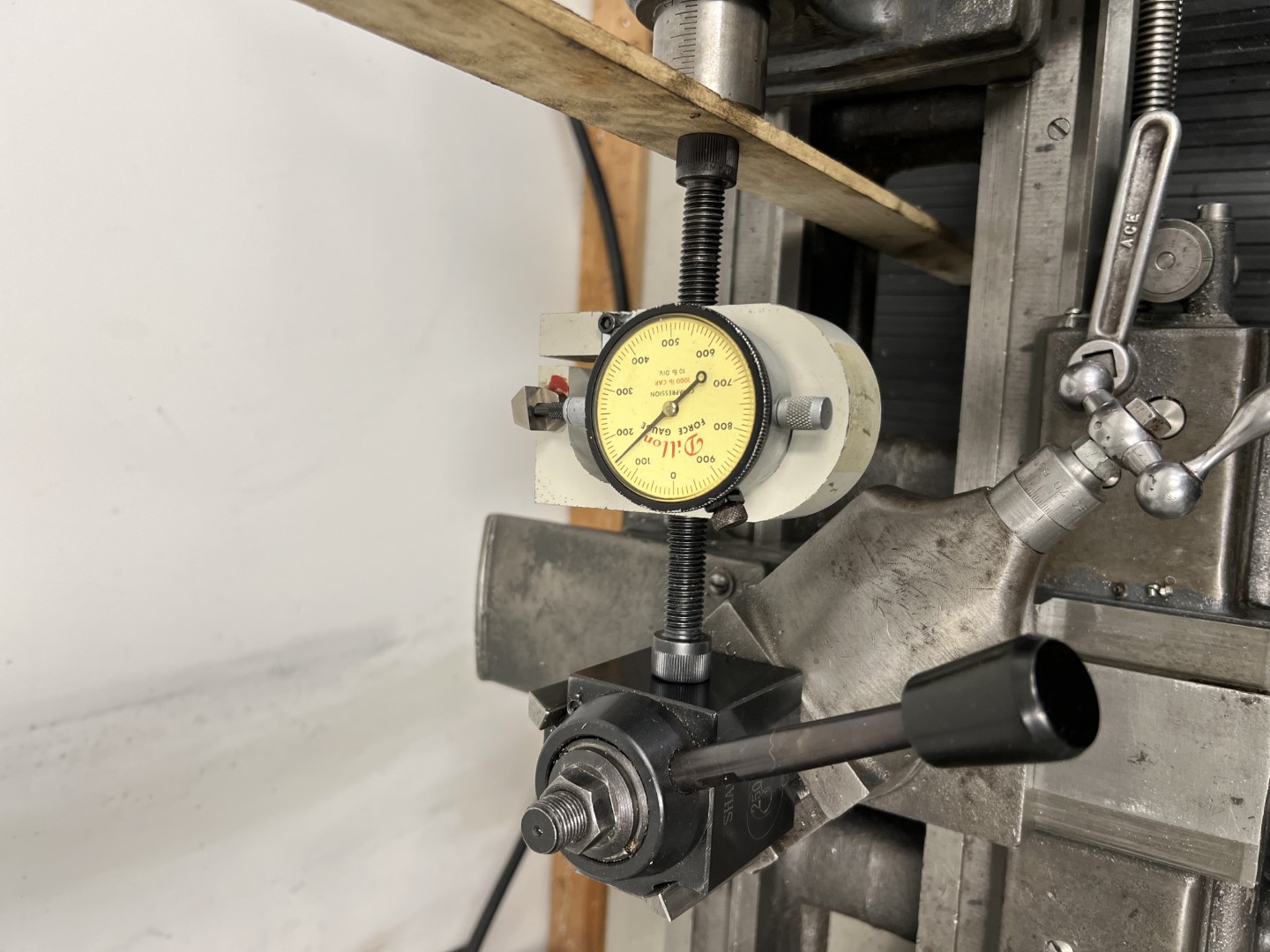
150lbs. Less than I expected to be honest, and much less than the common load capacity of 50% radial load capacity for single row ball bearings.
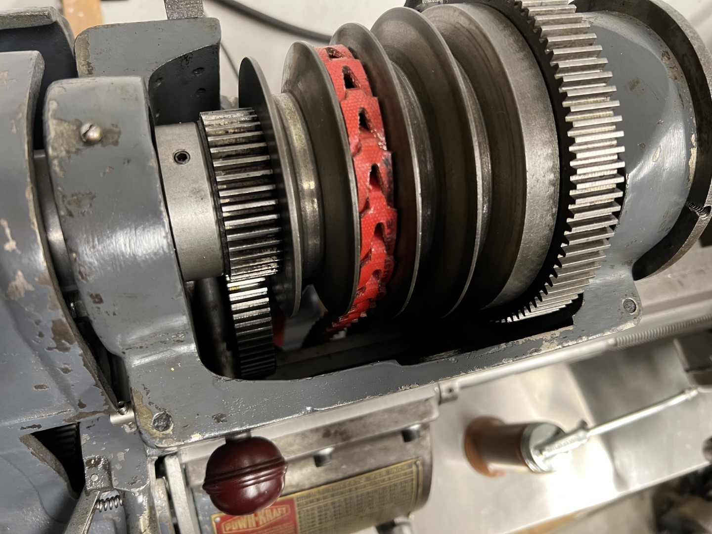
Headstock Drive
Initially, I intended to reuse the flat belt pulley arrangement. However, this comes with two significant disadvantages:
- A side tensioned belt drive requires significant room beside the lathe.
- A side tensioned belt drive pulls the lathe out of level when tensioned!
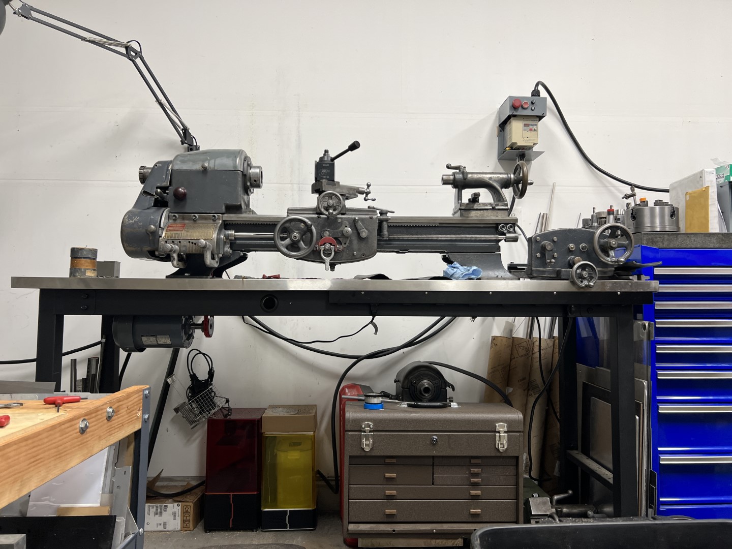
As a result, I endeavored to convert the machine to an underdrive as well.
In my shop, I had a spare 3-phase 1HP motor laying around, as well as a VFD that I scavenged many years before. These, in combination with a direct belt drive will run the lathe.
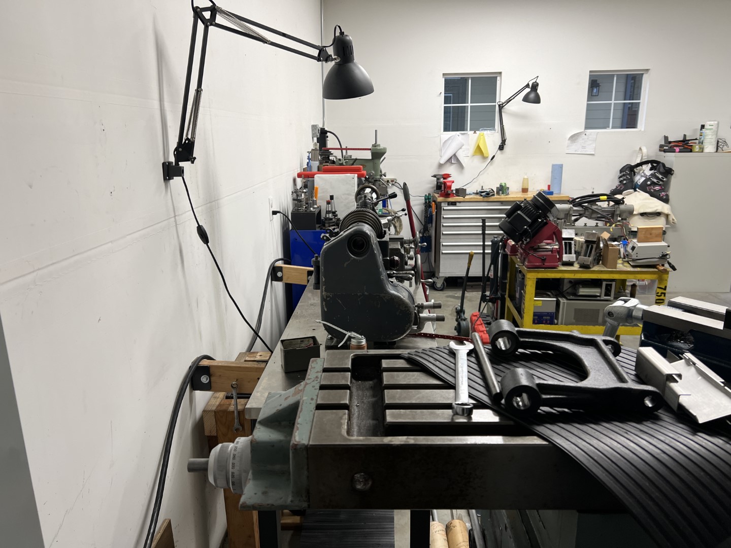
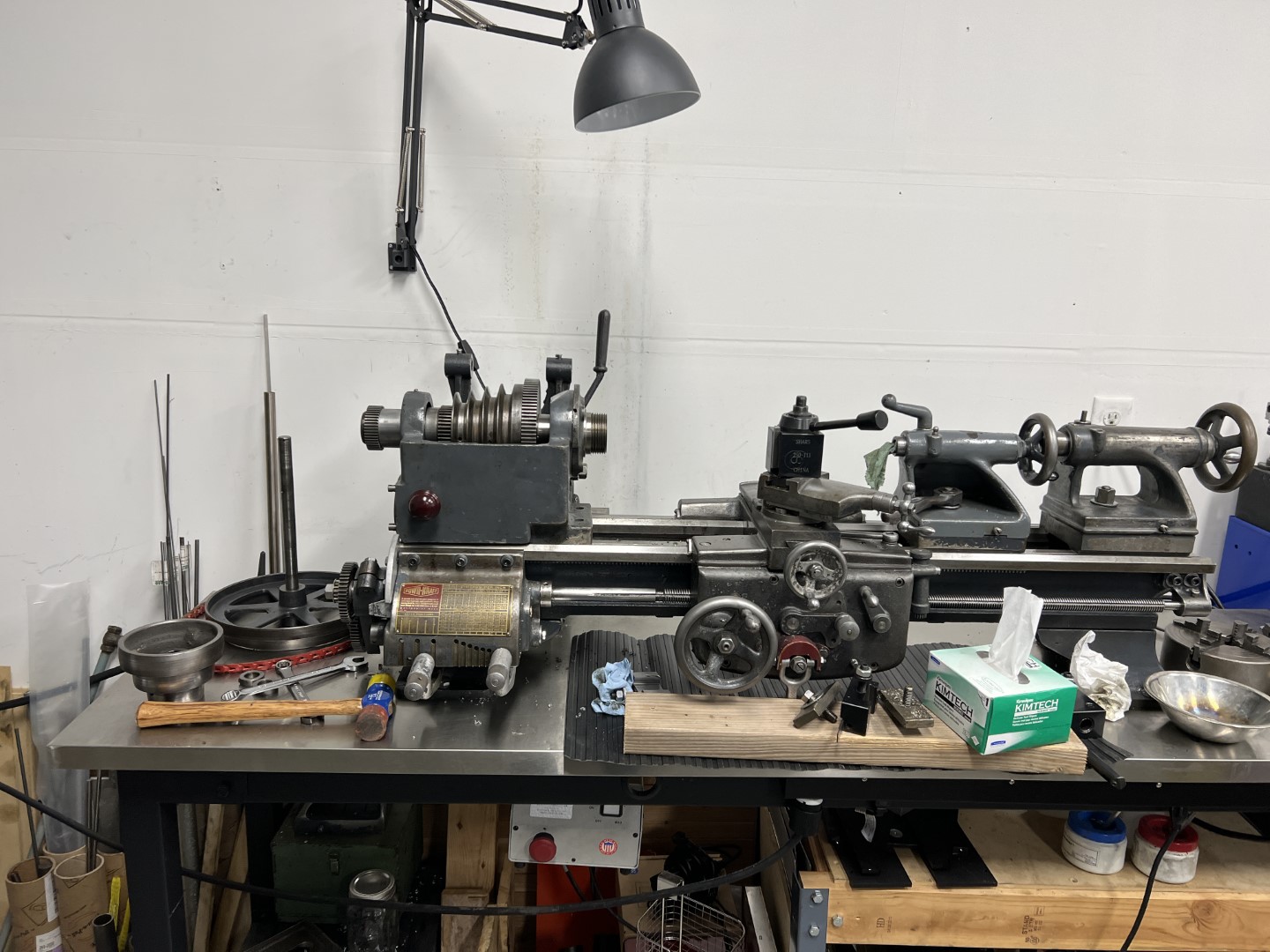
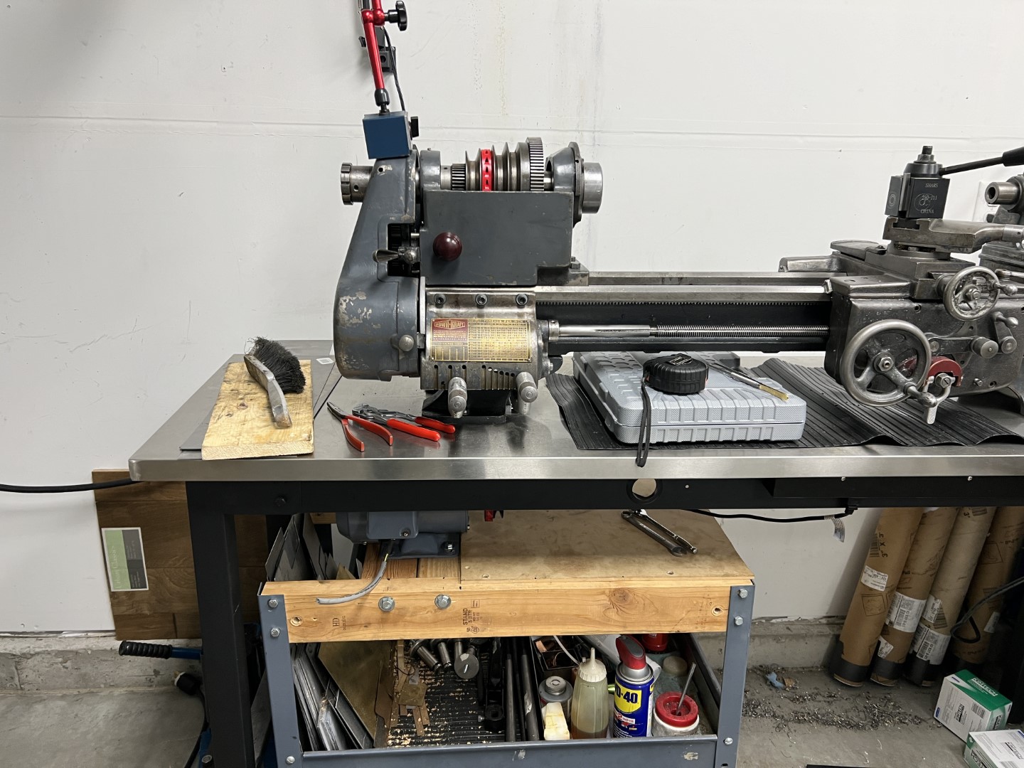
As can be seen here, significant space is available behind the lathe without the drive mechanism there.
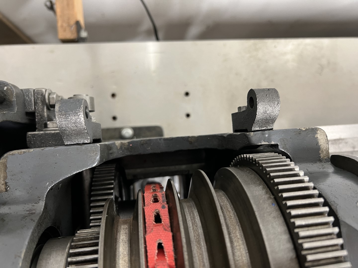
The same bed is used for underdrive lathes as well, so I knew it would have enough clearance for a belt. The underdrive lathes use a different drive pulley on the spindle though.
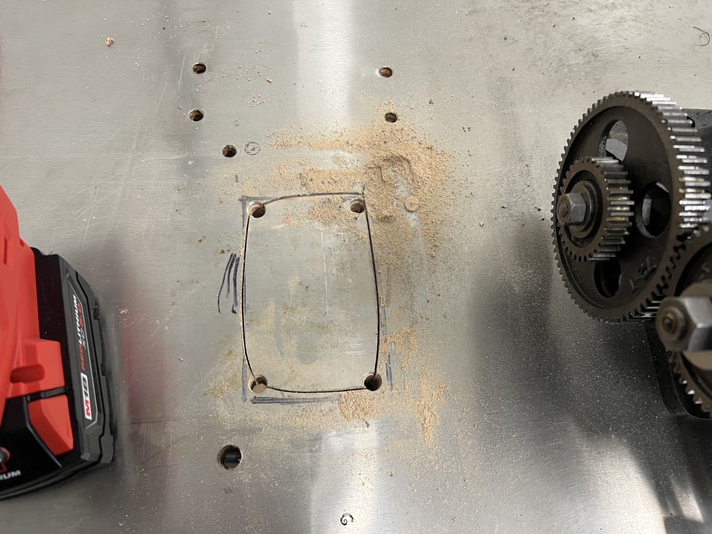
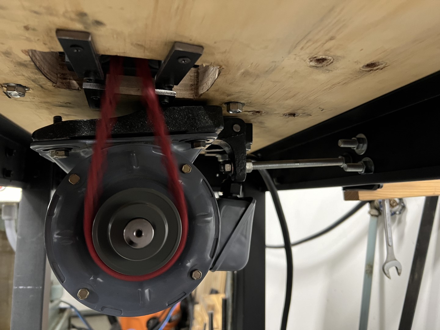
A hole was cut in the table:
And an idler guide developed to ensure clearance with the larger spindle drive pulley.
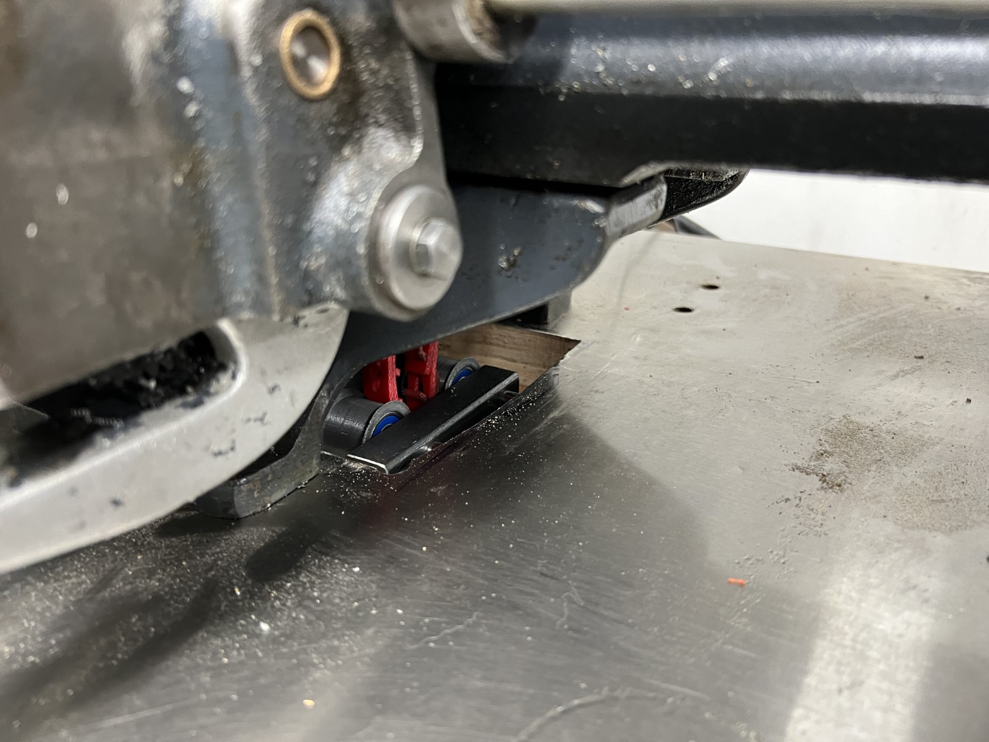
This will be redesigned later, as it provides unnecessary resistance and noise.
Initially, the underdrive was used with the same tensioning mechanism as before, only rotated
90 degrees.
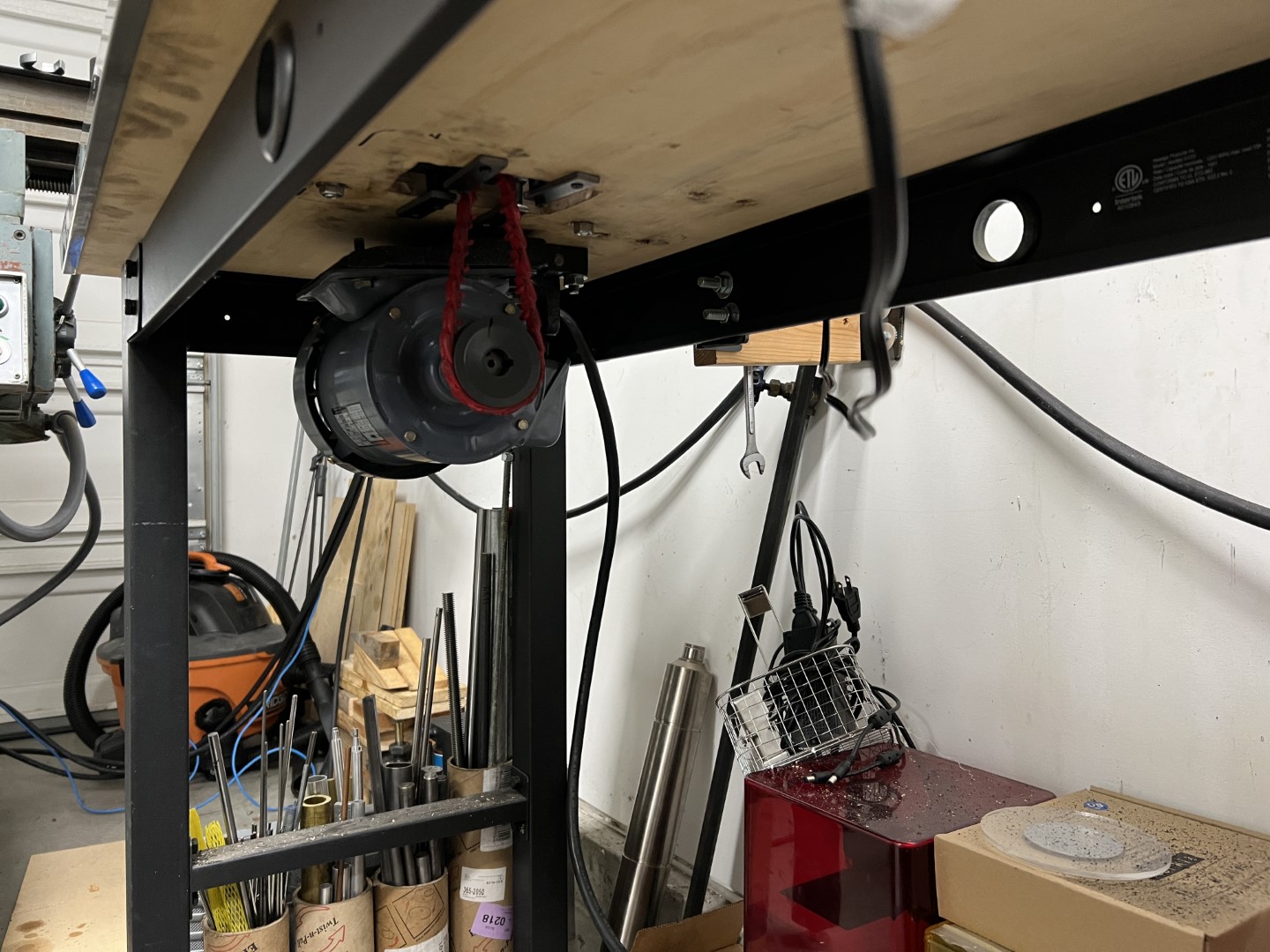
This proved undesirable, and as a stopgap, I bolted the motor to a cart underneath the lathe.
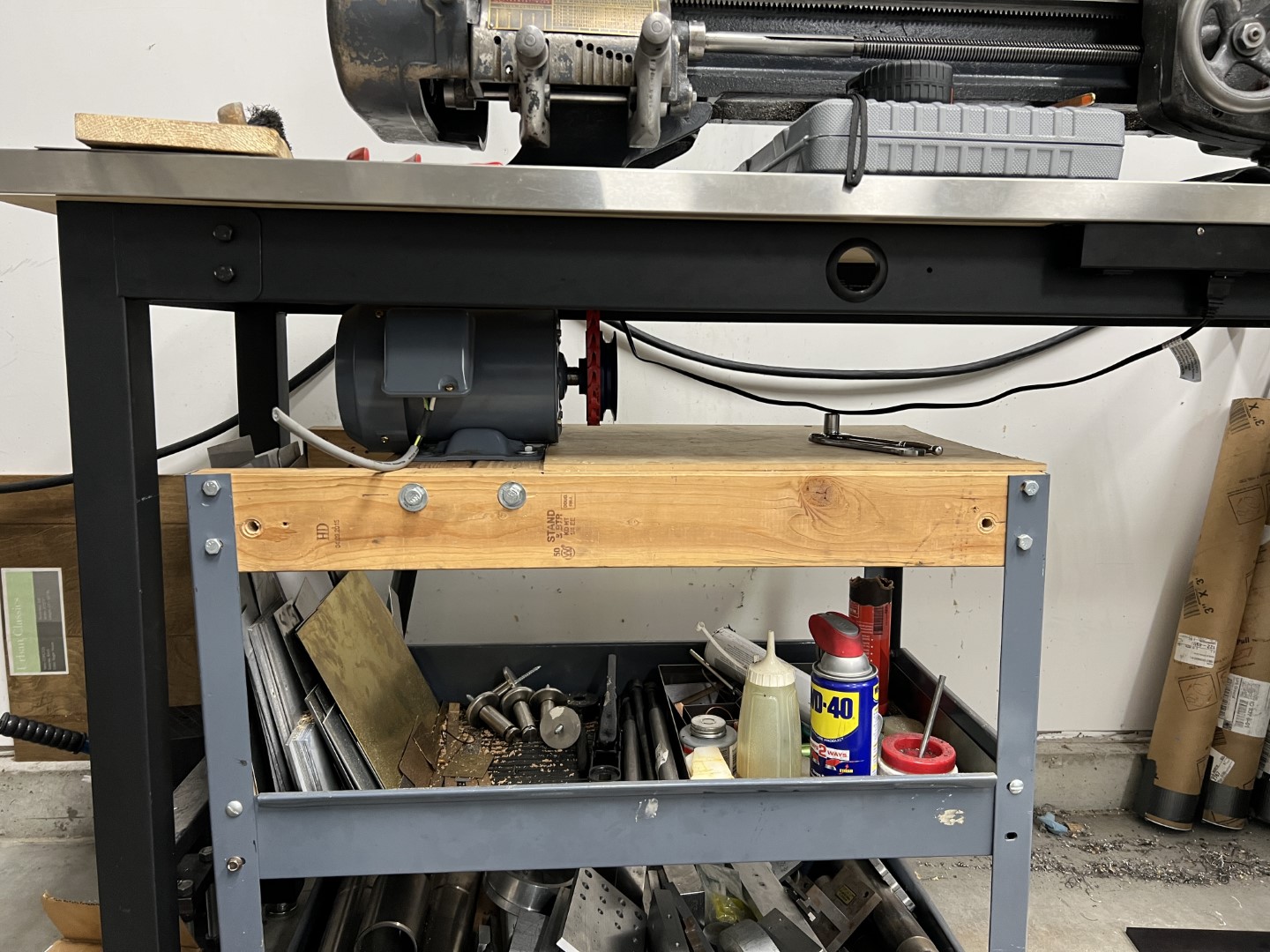
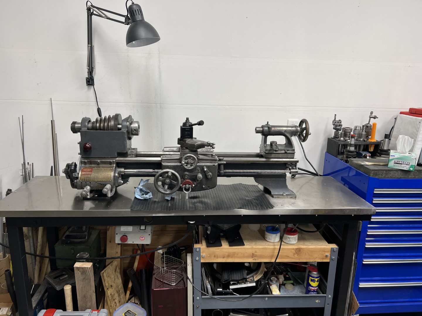
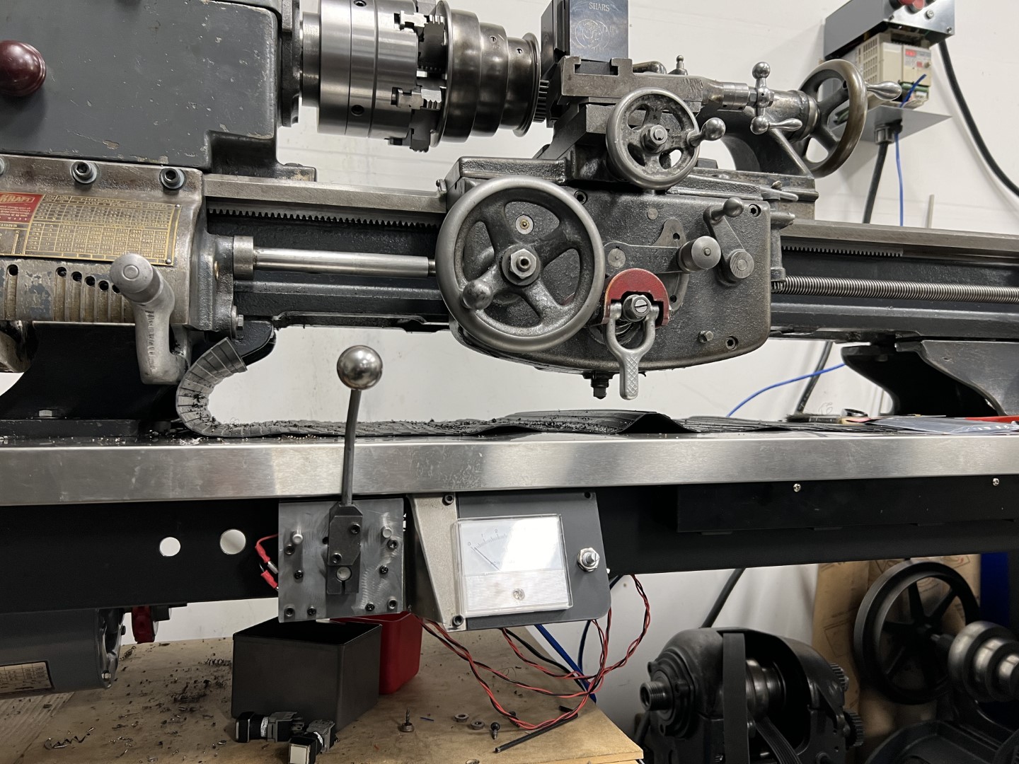
Ultimately, the motor is attached underneath the lathe with tensioner and drives the spindle directly.
This gives the lathe speeds of 0 - 1200RPM. However, the low torque is undesirable at low speeds. Fortunately the lathe has back gears.
Controls
In a VFD controlled machine, controls are naturally digital. Digital controls however, contrast with the 1950’s style of the lathe. I aspired to control the VFD with a lever for selecting forward and reverse, which would be accessible from the operator position of the machine.
A small enclosure was built (with a helping hand from my new press brake).
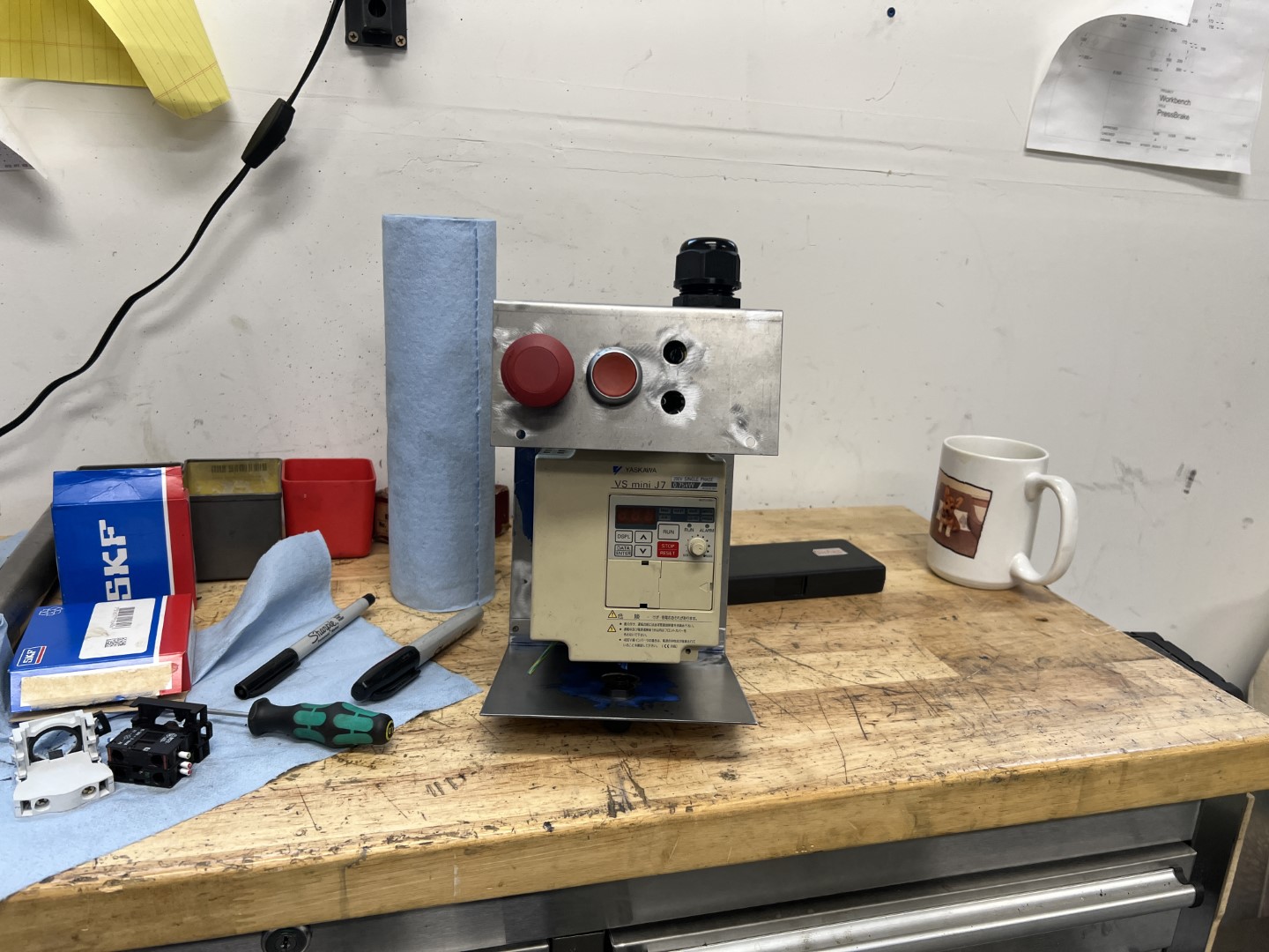
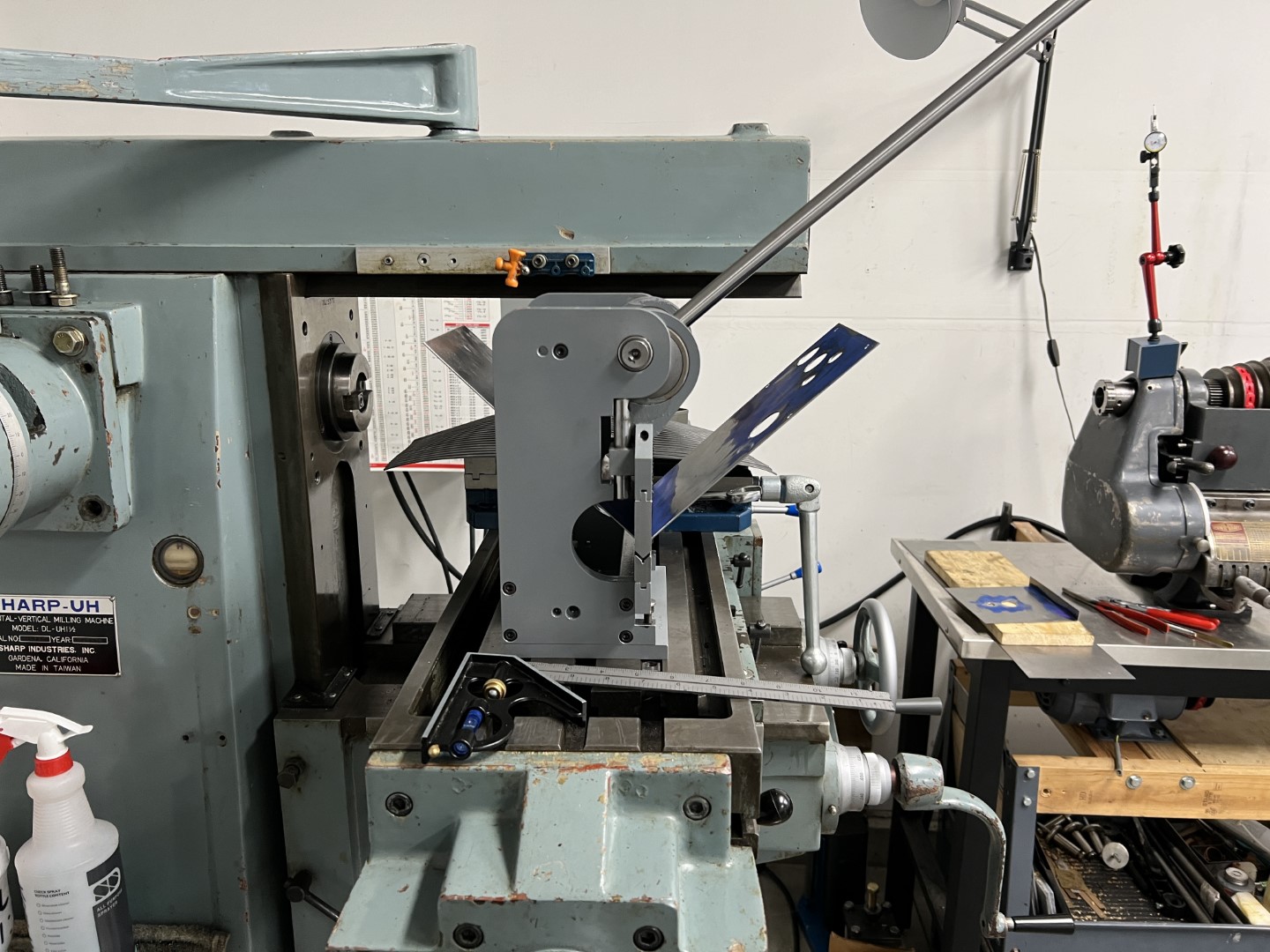
And a few design iterations produced a liveable lever operated forward and reverse, with speed control and motor amperage output to an analog gauge.
The Result
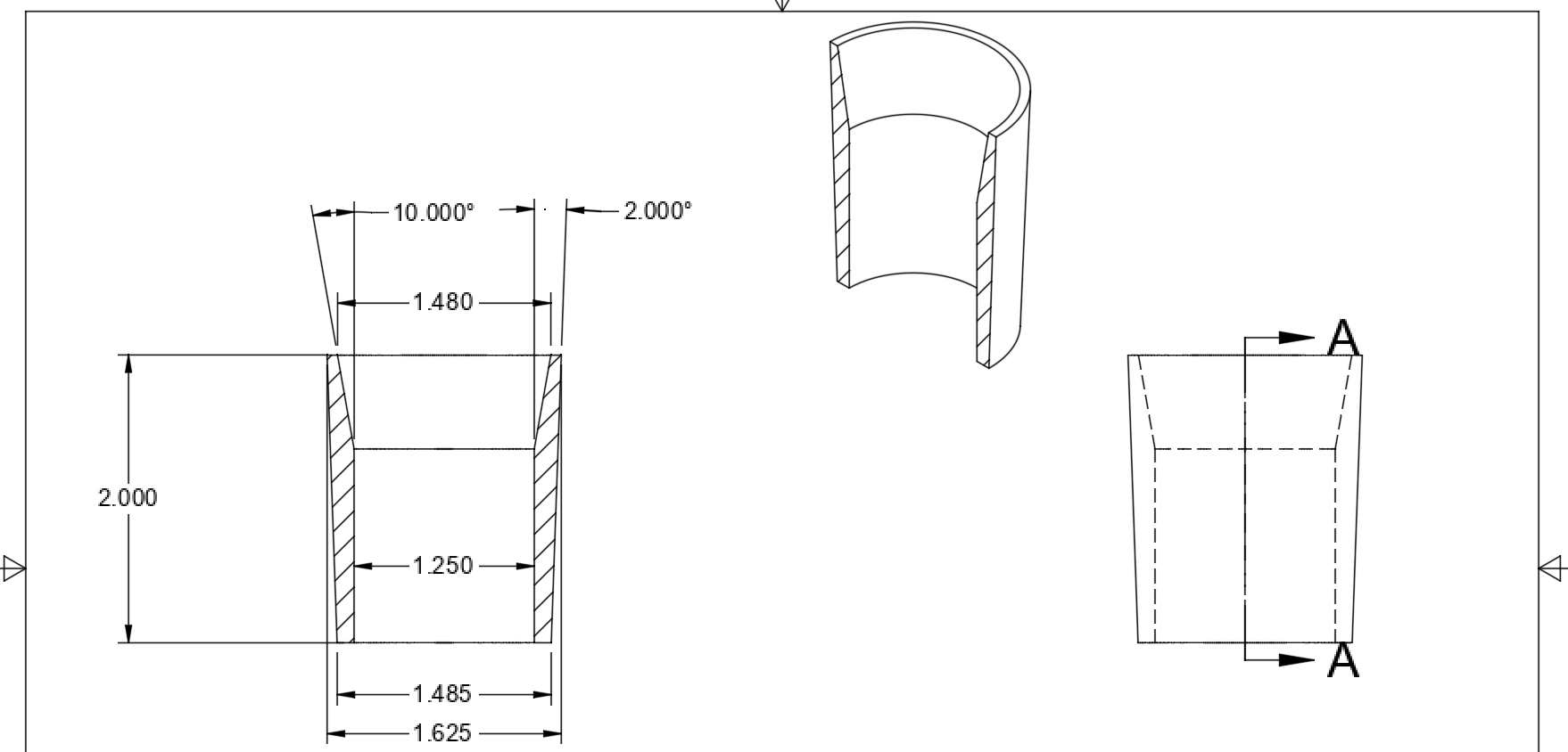
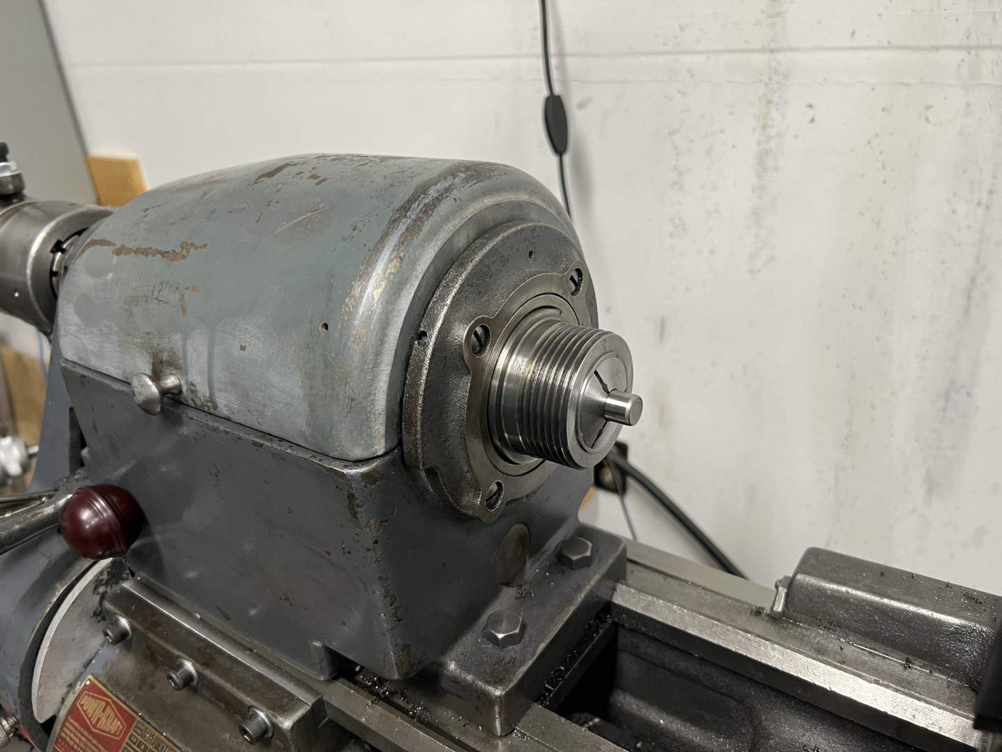
First project! Spindle adapter for 5C collets.
These are commercially available, and appear on eBay frequently, but for varying amounts of money. The commercial ones have an undesirable feature though, they protrude form the spindle by nearly 1/2”.
My design will be completely located inside the spindle. This will reduce the effective diameter of the spindle to 1-1/8” from 1-3/8”, but allow me to use collets in combination with a standard lathe chuck. This combination enables very efficient repeatability and location or alignment in common setups.
I did make both versions of the adapter:
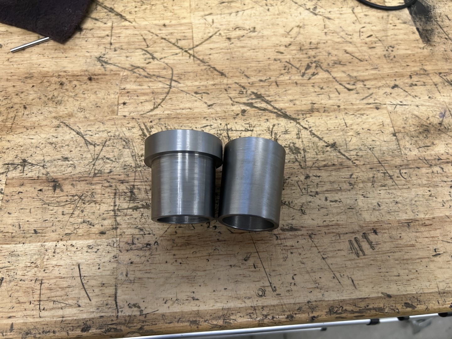
As can be seen, the collet fits nicely in the nose of the spindle.
This took several months of “hobby time” during which I also acquired an affordable collet-closer. A little bit of cleanup on it and I know have a remarkably modern lathe!